Welding Symbols Demystified!
If you want to read plans or drawings you have to know what the basic welding symbols are.
The main job of symbols is to convey to the welder where to weld, the joint type, how much filler material or metal is to be used, and how much of it needs to be in or on the joint, on a set of plans.
Side Bar: The American Welding Society (AWS) is responsible for creating the symbol standards.
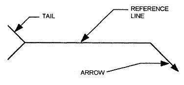
A welding symbol has three parts:
- Reference line: this is the main part of the symbol and it's function is to carry or provide all the information on the weld to be made.
- Arrow: this is what is used to point the reference line to where you need to weld.
- Tail: This is used to provide additional but important data as wells as information needed to complete the weld. For example it may contain information on what welding process is to be used, or something else of equal importance.
Welding Symbol Example:
Weld Symbol Or Welding Symbol? What's The Difference?
As discussed above a welding symbol conveys all the information a welder needs to know in order to complete a weld which is given to him or her on a set of plans or drawings (it has three parts to it)...
A 'weld symbol' is similar but different in that it is one specific symbol for one specific kind of weld.
In my article on the different types of welds I showed you the 5 basic welds: fillet, groove, surfacing, plug, and slot. There is a specific weld symbol for each of these weld types, which is just one small part of the entire welding symbol.
Basic Weld Symbols:
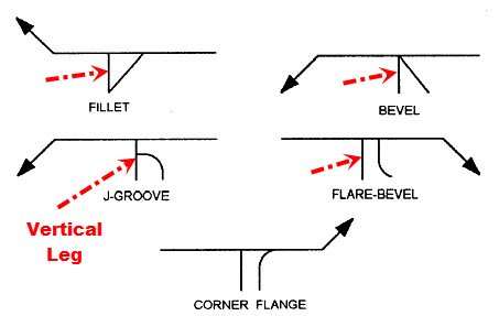
In the image below you'll see an actual weld symbol that is included on a reference line.
Do you see the line that is pointing down 90 degrees to the reference line? It's the vertical line that is pointing down. And drawn to the right of this vertical line (also called the vertical leg) is another slanted line. The vertical line and the slanted line complete the weld symbol. The vertical line is always to the left of the slanted line no matter what. That's the standard.
Weld Symbols On A Reference Line:
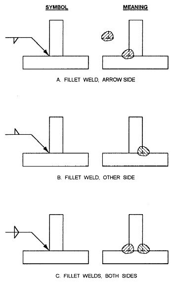
The images below will begin to put this symbol thing together for you because it shows you how they basically work using a very simple drawing example.
- As you can see in image A below the symbol for the weld is on the underside of the reference line. When the weld symbol is on the underside of the line it is called the 'arrow side'.
- In image B you can see that the symbol for the weld is on the top side of the reference line. When it's on this side it's called the 'other side'.
- And of course as you can see in image C below when both symbols are on both sides of the reference line that means that this type of weld (fillet weld) is to be performed on both sides.
Weld Location:
If you need to specify where a joint needs to be beveled and it needs to be beveled on one side you have to show the welder where on the joint.
The symbol below is such an indicator. As you can see, the arrow points to the piece to be beveled and it is slanted. That is how a bevel on one side of a joint is presented with a welding symbol.
Beveled Plate Symbol:
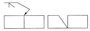
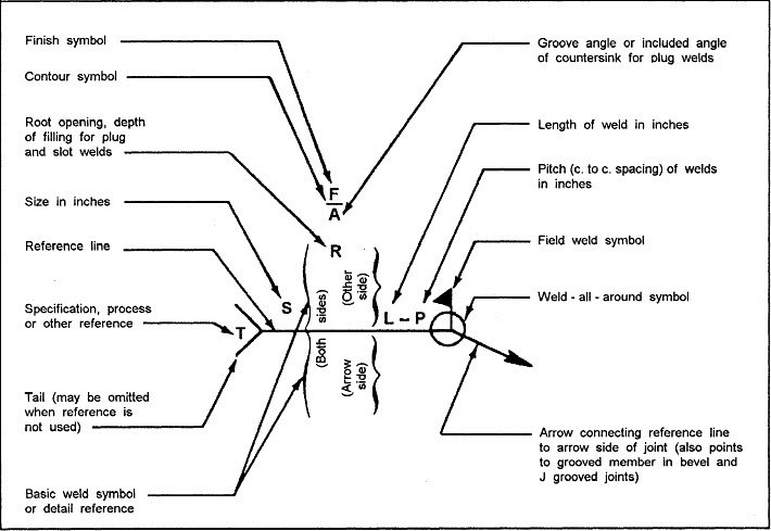
A lot of information can be included in a welding symbol. The diagram below gives you a breakdown of what one can include.
Note: All the information that is on a welding symbol's reference line should only be read from the left to the right.
Also, in regards to the welding symbol elements and breakdown diagram below, you can include dimensions of a weld such as the size, length, pitch (center to center spacing of the weld), the groove angle, and where the root opening of the weld should be. Where this weld and it's dimensions are located depends on the side of the reference line on which the weld symbol is placed.
Breakdown Of A Welding Symbol.
(Click Image For A Larger View):
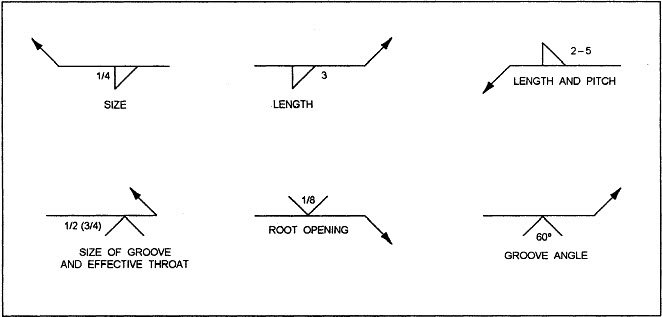
The diagram of welding symbols below shows you examples of how the different dimensions are provided in the symbols. These dimensions include:
- The Length.
- the Length and pitch.
- The Size of the groove and effective throat of a weld.
- The root opening of the weld.
- The groove angle of a weld.
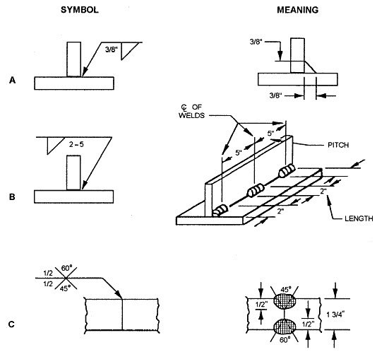
The diagram below reveals what the actual meaning of each symbol which describes a dimension is. As you can see, the left hand column lists the dimension Symbol, and the right hand column gives you the meaning of it.
- Image A: The weld size is to the left of the vertical leg (3/8 of an inch). On the right hand side you'll notice the pitch and length.
- Image B: This shows you two inch fillet welds which are intermittent (spaced apart), and are five inches away from each other but on center.
- Image C: This shows you the groove weld size. It's to be welded on both sides of the joint and they are .5 inches each. However, the groove is different on both sides. One groove is 60 degrees, and the other is 45 degrees.
Additional Symbols
Contour Symbols:
There are many occasions where more information needs to be conveyed to the welder beyond the basic welding symbols shown above.
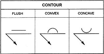
Lets begin with the Contour symbols. These additional welding symbols are used along with weld symbols which provides information on the weld face and how it is to be formed.
Finish Symbols:
There are also symbols that are called 'finish symbols'. These symbols show the welder how to actually create the contour. Keep in mind the word 'finish'.
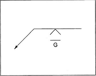
The finish symbol reveals how to finish a weld. For example the following letters are used to convey this information on a symbol:
- C = chipping
- M = Machining
- G = Grinding
For example there is a G, as shown below, so the welder needs to grind the weld to create the contour that is needed, and the actual contour is to be 'flush'. This means that the weld needs to be ground down so that it is flush with the base metal.
Weld All Around and Field Weld Symbols:
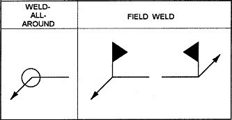
The weld all around symbol indicates that you have to keep welding the joint all the way around. It's simply a circle...
If there is a welding job that need to be taken care of and it's not possible to do it in the welders shop then a field weld symbol is used to convey this information. As you can see below a field weld symbol kind of looks like a flag which points away from the reference line arrow and toward the tail of it.
And Even More Information...
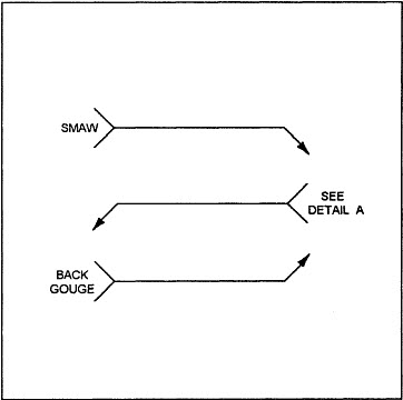
There are times when you need to tell the welder what kind of filler metal or process is needed, or something else important to completing the job properly. The way this is accomplished is to create a tail at the end of the reference line, as you can see below. And in this tail area that looks like a fish tail you will include a written message.
Multiple Welds:
There are many cases where you'll need to do more than one type of weld on a joint. For example, maybe you are fabricating a special part or something like that...
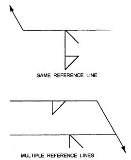
Lets say for example you need a welder to accomplish both a fillet and bevel groove weld on the same joint. You can provide this information in symbol form as shown below. As you can see the welder is to first do the bevel groove weld, and then complete it with the fillet.
There are two welding symbols here. The reason for this is to illustrate the fact that you can convey the same information using one or two reference lines.
Putting It All Together:
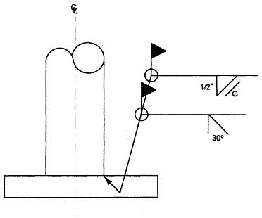
Below is an illustration of how a welding symbol look on a set of plans.
It shows that a column of steel pipe need to welded onto a base plate.
Here is what the symbol is saying:
- This job is to be done in the field.
- Bevel the pipe 30 degrees.
- Weld all around it using a bevel groove weld.
- Do a .5 inch fillet weld and weld it all around.
- Complete it by grinding the weld down so that the welds contour is flush.
Welding Plans:
New! Welding Table
New! Log Splitter
Top Projects:
