How Build A Go Kart Frame!
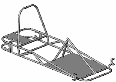
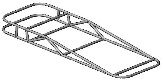
If you think the go kart frame on this page is 'bad', then you are going to think this one is 'super bad'. We put a lot of work into the design, and even more work into the step by step directions on how to fabricate it.
Let us know what you think. Now lets get started with the build starting with the materials you need to get it done.
Bill Of Materials:
- 42 feet of round tubing: 1.00 inch outside diameter x .058 inch wall.
- 2.5 inches x 6 inch mild steel sheet: 11 gauge.
- 4 inch x 8 inch mild steel plate: .25 inch.
- 4 inch x 12 inch mild steel sheet: 14 gauge.
- 23 inch x 22 inch mild steel sheet: 16 gauge.
SUGGESTED TOOLS:
- Tube bender with a bending die for ¾” tubing, 4” bend radius.
- Hole saw cutting tool (such as a Joint Jigger™ or similar brand).
- Hole saw, ¾” diameter.
- Bend grinder with ¾” wide grinding wheel.
- Flat work surface.
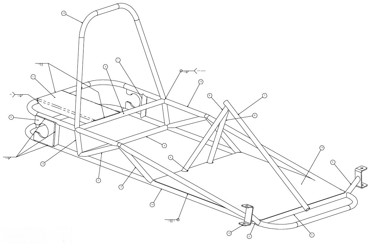
Go Kart Weldments:
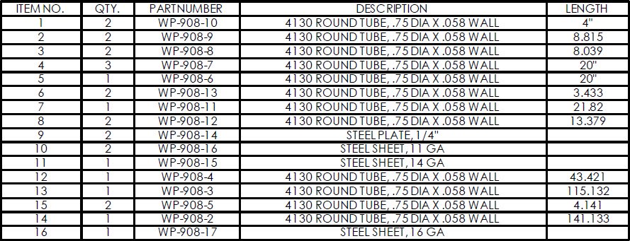
List Of Parts:
Go Kart Frame Project Notes:
- This project is intended to be completed using either MIG, TIG, or Oxy-Acetylene weld processes. However, if either TIG or the Oxy processes are used, the weld joints need to be particularly tight.
- Whenever you make more than one bend in a tube form that must remain flat, pay particular attention to the plane of the tube prior to each bend. Otherwise, the tube form may become unusable. This can be accomplished by adjusting the height of a take-up table or surface to correspond to the bottom of the tube. This is best done before any bends are made, while the tube is resting in the bending die.
- You can get more detailed 22 page PDF set of this go kart frame plan set here. Or you can get the one page pdf version of the above weldments here in PDF format.
24 Steps To Building A Killer Go Kart Frame!
Step 1: Referring to the cut list on page one of the drawing, cut a length of ¾” X .058 tubing for part number WP-908-2.
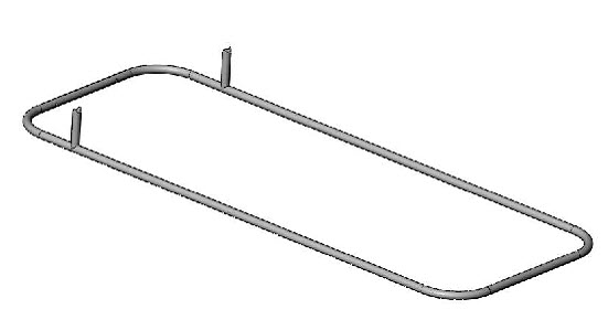
Step 2: Using a tube bender with a ¾” X 4” bending die, make the bends in the tube to create part number WP-908-2 as shown on the drawing.
This will be the bottom of the go kart frame.
After all bends are made, this part will be a rectangle. Make sure the tube ends are within a 1/16” from each other and facing each other in the middle of one of the shorter legs of the rectangle, as noted on the drawing.
Step 3: Weld the ends of the tube rectangle together. This should be a flat weld bead all the way around the tube. Make sure the “frame bottom” lays flat on the work surface before and after it is welded.
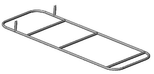
Step 4: Cut the length of tubing for part number WP-908-3.
Step 5: Similar to the above steps, make the necessary bends to create part number WP-098-3.
Step 6: Most hole saw tools will not make long, shallow cuts like the ones at the ends of part number WP-908-3. This is due to the limited travel distance of the hole saw. An effective method of preparing these tube ends for the joint is by forming them on a bench grinder. This is a common method of creating a “Fish-mouth” in the ends of tubing used in aircraft construction. It is done by using a dressing wheel to create a radius to the face of a grinding wheel.
The width of the grinding wheel must equal the diameter of the tubing to which the part will mate- in this case, ¾”. After the grinding wheel face has been shaped (radiused), the tube end can be formed by holding the end of a tube at the correct angle while grinding a concave or “fish-mouth” necessary to create the joint geometry.
It is advisable to practice first on a piece of scrap tubing. Be sure to work slowly and check the fit often. It won’t take long to get a feel for how much to grind. The results can be surprisingly good.
Step 7: Cut tubing and make the necessary end cuts for part numbers WP-908-5, WP-908-6, WP-908-7, WP-908-8, WP-908-9, and WP-908-10. Always check the fit of the tube where there is contact with another tube, in other words, at the joints.
Step 8: Place the frame bottom, WP-908-2, on the flat work surface. Clamp it in place, or place weights on top so it will not move easily.
Position a WP-908-10 on one side of the frame bottom as indicated on the drawing. Make sure this tube is vertical and perpendicular to the long side of the bottom frame. Tack weld in place.
Step 9: Repeat on the other side of the frame bottom.
Step 10: Place part numbers WP-908-6, and WP-908-7 between the frame bottom and in the locations indicated on the drawing. Tack weld in place.
Step 11: Place part numbers WP-908-3, WP-908-5, WP-908-8, and WP-908-9 on the go kart frame bottom as indicated on the drawing. Hold these parts in place with clamps, magnets, or wire. Recheck placement and fit after they have been secured in place. There should not be more than a 1/16” gap between parts at the joints.
Step 12: Tack weld each tube at the joints. Make sure the frame bottom is still flat on the work surface. Complete the welds at each joint, alternating from one side of the frame to the other.
Step 13: Cut a length of tubing and bend according to the drawing to make part number WP-908-4. This is the roll-over bar/seat back.
Step 14: Position the roll-over bar on the frame according to the drawing. Check the fit at the tube ends. Tack weld in place at both ends of the tube. Recheck placement and fit and complete the welds.
Step 15: Make part number WP-908-13. Position each part (one at a time) on the frame and check the fit. Tack weld each tube at the correct angle, making sure both parts are in-line with part number WP-908-6 (front crossmember).
The position, placement, and angle of these parts directly effect the tracking: and steering of the go kart. Once this has been assured, complete the welds.
Step 16: Cut part number WP-908-16 (qty 2) from the 11 GA sheet. Bend the plates as indicated on the drawing. Note: use the flat pattern dimensions when cutting the parts out of the sheet.
Step 17: Weld WP-908-16 in place one at a time as indicated on the drawing. The position, placement, and angle of these parts also affect the tracking and steering of the go kart. Special care should be taken to assure they are correct on the frame before and after welding.
Step 18: Cut and prepare the ends of part number WP-908-12 (qty 2). Cut a length of tube for part number WP-908-11.
Step 19: Position these tubes on the go kart frame as
indicated on the drawing. Check the joint fit and tack weld in place.
Then complete the welds.
Step 20: From the 16 GA
material, cut part number WP-908-17. Place this part on the frame and
weld in place. To eliminate or avoid warping the plate, or causing
misalignment, begin by tack welding the plate at each corner and in the
middle of each edge.
Step 21: Cut part number WP-908-14
from the ¼” plate material. Tack weld in place. Check placement
referencing the drawing. Complete the welds. These plates are the go
kart frames rear axle bearing mounting plates. The details of the
bearing mounting holes have been omitted due to the various bearings
that are available and may be preferred by the builder.
Step 22: Cut part number WP-908-15 from the 14 GA material, using the flat pattern dimensions. Make the indicated bends in the part This part is the engine mount bracket. The engine mount bolt pattern has been omitted due to the various engines available and preferred by the builder. The particular mounting holes can easily be drilled in the bracket after welding.
Step 23:Place the engine mount bracket on the frame and position as indicated on the drawing. Check the fit and tack weld in place. Complete the welds. At this point the basic go kart frame is complete. Items not included in this plan set are the spindles, gas and brake pedals, steering shaft and bellcrank, seat and seat mounting. All these items are readily available, off-the-shelf items that do not need to be fabricated.
Copyright WcWelding.com All Rights Reserved.
Welding Plans:
New! Welding Table
New! Log Splitter
Top Projects:
