Low Profile Oil Drain Pan Project!
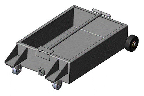
The lowest price for a low profile oil drain pan that is of decent quality (not the cheap plastic ones) is around $150. The better ones are in the $198 - $250 range. For a fraction of that price you can buy the materials and build your very own! Check this out...
This plan set is for the construction of a Low Boy (low profile) oil drain pan. This will be a welcomed addition to any home garage or commercial shop. It can be welded by either MIG or TIG methods.
Special attention should be paid to the corner welds of the sheet metal oil pan. These welds must be leak-proof to avoid messy spills and clean up in your shop during use.
MATERIALS REQUIRED:
- 28 inches x 26 inches mild steel sheet: 16 Gauge.
- 3 inch x 1.5 inch mild steel sheet: 14 Gauge.
- 1.25 inch x .5 inch x 1.25 inches long, mild steel rectangular bar stock.
- 37 inch mild steel round bar stock, .5 inches in diameter.
- 3 inch continuous hinge: .06 inches thick x approximately 2 inches open width x 1/8 inch diameter pin.
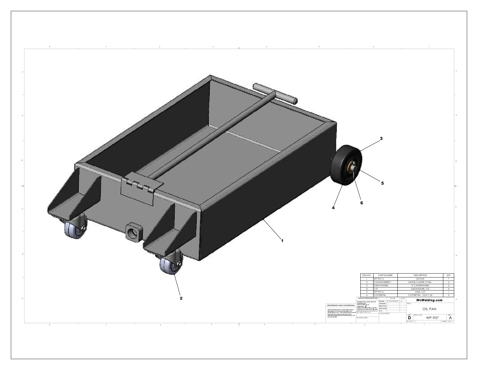
- 2 Swiveling casters: 2 inch diameter wheels.
- 2 caster wheels: 3 inches in diameter.
- 4 SAE washers: .5 inch.
- 2 Cotter pins: 1/8 inch x 1.25 inch long.
- Suggestion: 1 Brass Ball valve, .5 inch NPT female –.5 NPT male.
Oil Drain Pan Assembly:
Assembly List:

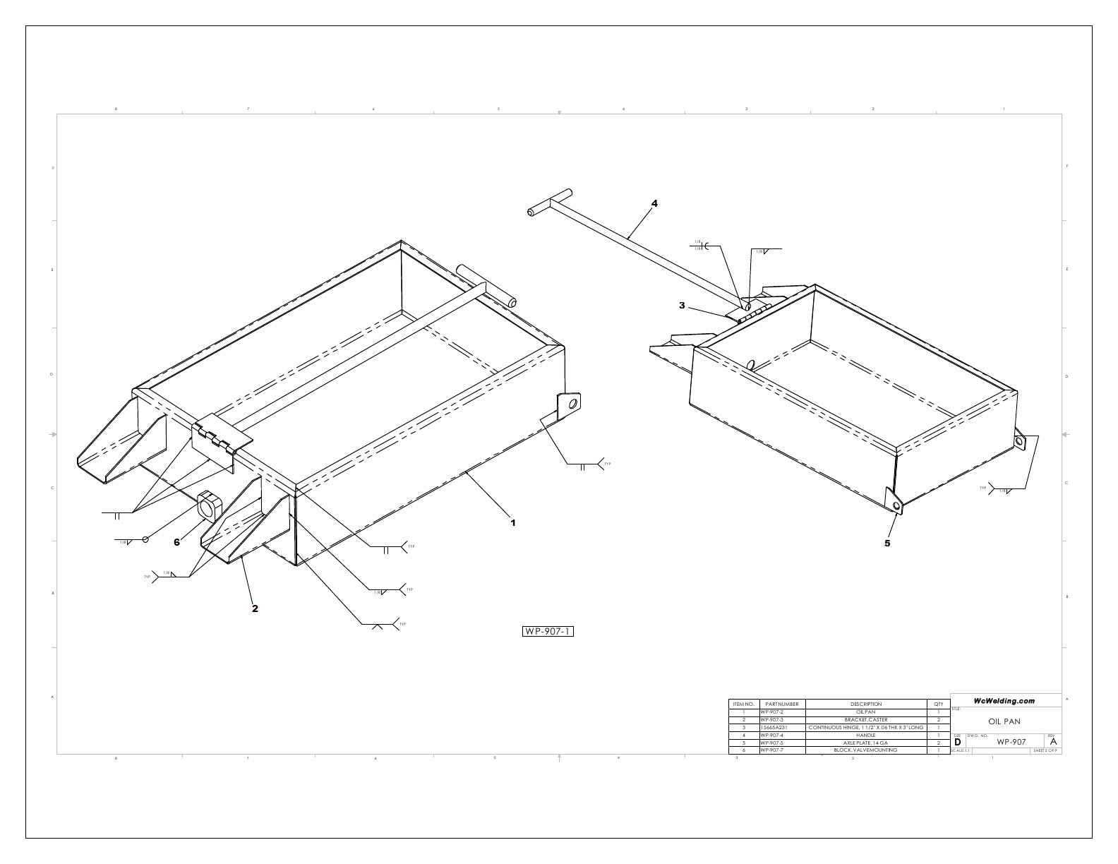
Oil Drain Pan Weldments:
Weldments List:

How To Fabricate A Low Profile Oil Drain Pan In 19 Steps!
You may want a better visual of the weldments for this so you can view a one page pdf of them here. Or you can get the 14 page set of plans for this here instead. Otherwise here is how to build the low profile oil drain pan in nineteen steps...
Step 1: Cut out the flat pattern for part number WP-907-2.
Step 2: Using a box/pan brake, fold the flanges as shown on drawingWP-907. Begin with the 5/8” flange that goes around the top of the pan. Next, bend the 4 ½” flanges. The corners should come together with minimal gaps.
Step 3: Using either a Mig or Tig welder, tack weld the top flanges together. Then proceed to weld the corners together starting from the bottom pf the pan and working toward the top flange. Hold the bottom of the pan flat against the work surface as you weld.
Step 4: Cut out the flat pattern for part number WP-907-3 (2 req’d).
Step 5: Using a bending brake, make the bends as per the drawing.
Step 6: PositionWP-907-3 as indicated on the low profile oil drain pan drawing and tack weld to the pan (WP-907-2). Place a tack at the top of each flange leg (top of part as shown on drawing), and at the bottom of the WP-907-3 bracket
Step 7: Completely weld both caster brackets (WP-907-3) to the pan.
Step 8: Cut out (2) part number WP-907-4 (axle plates).
Step 9: Position theWP-907-5 axle plates on the pan as shown on the drawing. Tack weld in place, then complete the welds.
Step 10: Cut a section of 1 ¼” x ½” barstock to 1 ¼” long. Drill and tap a ½” NPT Pipe thread hole exactly in the middle of the block. This creates part number WP-907-7.
Step 11: Weld the valve block, WP-907-7, to the front of the pan. Make sure the block is positioned correctly, with the pipe thread hole concentric with the ¾” hole in the pan.
Step 12: Position the 3” section of continuous hinge on the pan as indicated on the drawing. Tack and weld in place.
Step 13: Cut the various lengths of ½” round barstock to make the handle, WP-907-4. Weld the two pieces together per the drawing.
Step 14: Weld the handle to the continuous hinge.
Step 15: Paint or powder coat as desired.
Step 16: Attach the casters to the WP-907-3 brackets. The details of this attachment have been left out due to the various hole patterns from one brand of caster to another.
Step 17: Slide the axle rod, WP-907-6, through both axle plates and roughly center it on the pan.
Step 18: Attach the 3” caster wheels with a SAE washer on either side of the hub. Hold in place with a 1/8” x 1 ¼” cotter pin.
Step 19: Screw a ½” NPT valve of your preference into the WP-907-7 valve block. A suggested valve is a brass ball valve with a female thread on one end and a male ½” NPT thread on the other end.
Congratulations. You have a one of a kind welding project completed: your very own hand fabricated low profile oil drain pan. Now send us your pictures and details...please!
Similar Welding Projects:
Copyright WcWelding.com All Rights Reserved.
Welding Plans:
New! Welding Table
New! Log Splitter
Top Projects:
